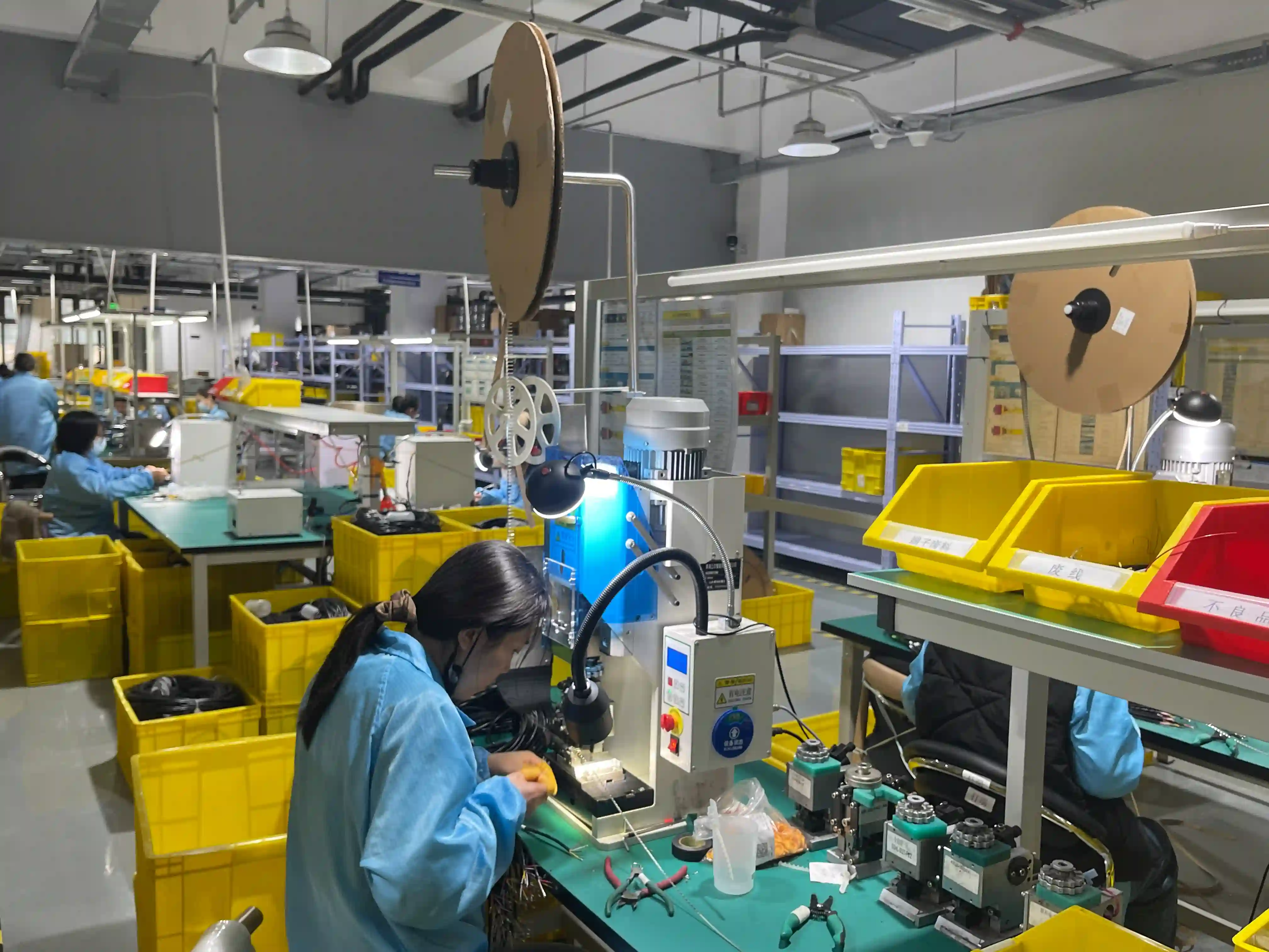
In a representative pilot build, our team reviewed a batch of automotive branch splices where the first welding setup passed continuity but produced an unacceptably wide resistance spread across the splice group. After tightening collapse-distance limits and rejecting unstable stack layouts, the spread tightened substantially and the destructive pull samples broke in the conductor instead of the weld. That is the difference between ultrasonic wire splicing as a machine operation and ultrasonic wire splicing as a controlled harness process.
Ultrasonic wire splicing uses high-frequency mechanical vibration, pressure, and short cycle time to create a solid-state bond between conductors. Public references on ultrasonic welding explain the physics, while harness production has a more practical question: can the supplier repeat the same weld across every lot, shift, wire bundle, and operator change? This guide answers that sourcing question.
The discussion is written for engineers and buyers moving from prototype to production. It assumes the reader already has a harness drawing, a preliminary splice stack, and a need to compare welding against crimped or soldered splice methods. For related process context, see our ultrasonic welding capability, butt splice selection guide, and pull force testing guide.
20-40 kHz
Common ultrasonic welding frequency range
4 signals
Energy, time, pressure, and collapse tracked
3 samples
Minimum setup pieces we prefer before release
<60 s
Typical operator decision time for pass/fail checks
In This Article
When ultrasonic splicing is the right choice
Ultrasonic splicing works best when one splice must join several conductors with low resistance and limited package size.
The common win is a branch junction inside an automotive, appliance, battery, or industrial harness where a bulky barrel splice would create routing stress. Instead of compressing the wires inside a metal sleeve, the ultrasonic welder scrubs the conductor surfaces together under force. Surface oxides break up, strands consolidate, and the stack becomes one compact metal joint.
The process is especially useful for copper-to-copper multi-wire stacks and selected copper-to-aluminum transitions. It is less attractive for field-serviceable joints, very low-volume repairs, or designs where the splice stack changes every build. In those cases, a controlled crimped or soldered connection may be easier to release.
the review do not approve ultrasonic splicing because the machine can weld. the review approve it when the splice stack, pull result, milliohm reading, and cross-section evidence all point to the same stable process. IPC/WHMA-A-620 gives the workmanship language; the factory must add measurable release limits.
OurPCB Engineering Team
Process window and setup controls
A weld schedule must define what the machine controls, what the operator checks, and what the quality team records.
The critical weld inputs are amplitude, clamp force, weld energy, weld time, stack height, and tooling condition. A stable process does not rely on one magic number. It uses a window where several signals agree. If energy climbs while collapse distance shrinks, the wire stack may be dirty, too tight, or incorrectly layered.
We call this the four-signal check: energy, time, pressure, and collapse distance must all make sense together. In production, the useful record is not only a green pass screen. The useful record shows the approved schedule, machine ID, anvil/horn set, wire lots, first-piece results, and the sampling rule used during the run.
Standards should be named in the release plan. Use IPC/WHMA-A-620 for wire harness workmanship expectations, UL-758 when the assembly uses appliance wiring material requirements, and IATF 16949:2016 when the welded splice is part of an automotive quality system. Public background on IPC electronics standards, UL safety certification, and IATF 16949 is stable enough for buyers who need a quick reference before reviewing the actual controlled standards.
Ultrasonic vs crimp, butt splice, and solder
The splice method should match geometry, service needs, current level, volume, and inspection evidence.
| Method | Best Fit | Key Controls | Limitations | Inspection |
|---|---|---|---|---|
| Ultrasonic wire splice | Multi-wire junctions, battery leads, mixed-metal transitions | Energy, amplitude, clamp force, time, collapse distance | Needs validated stack geometry and trained setup | Pull force, milliohm resistance, visual and section checks |
| Open-barrel crimp splice | High-volume copper splices with approved applicators | Crimp height, applicator shut height, wire range | Less flexible for odd wire-count stacks | Crimp height, pull force, bellmouth, conductor brush |
| Closed-barrel butt splice | Inline repair or simple wire extension | Die match, strip length, barrel fill | Adds length and may be bulky in branches | Pull force, sleeve damage, seal recovery |
| Soldered wire splice | Low-volume builds or specified legacy designs | Heat input, wetting, insulation distance | Wicking can create a fatigue point | Wetting, strain relief, insulation clearance |
| Mechanical junction block | Serviceable control panels and field wiring | Torque, ferrule fit, wire prep | Larger envelope and possible torque drift | Torque mark, tug check, continuity |
The table shows why ultrasonic welding is a process decision, not a universal upgrade. If a service technician must open and remake the joint, a junction block or crimped splice may win. If the harness needs a compact branch with repeatable low resistance, ultrasonic splicing usually earns its tooling and validation time.
The practical sourcing question is whether the supplier can explain the rejection mode. A vague answer such as "the machine alarms" is not enough. A useful answer names the failed signal, the likely root cause, and the containment action before the next lot starts.
Quality plan and release evidence
A welded splice should be released with measurable evidence, not only visual acceptance.
Approved splice stack drawing with wire sizes, strip lengths, and layer order.
Weld schedule showing energy, time, amplitude, pressure, and collapse limits.
First article photos plus destructive pull-force results for the released setup.
Milliohm resistance data for the splice group and customer-defined maximum drift.
Cross-section or peel evidence for high-risk automotive, EV, or mixed-metal joints.
Lot traceability for wire, machine ID, tooling set, operator, and inspection status.
For buyers, the most useful supplier question is direct: what would make you stop the line? Good answers include out-of-window weld energy, poor nugget geometry, pull failure at the weld interface, resistance drift beyond the approved limit, missing strand capture, or tooling wear. Weak answers focus only on visual shape.
Pair welded-splice release with first article inspection before volume production. The FAI package should show that the splice survives mechanical, electrical, and workmanship checks. For sealed harnesses, add adhesive-lined heat shrink controls or molded protection so the weld does not become a corrosion site.
A welded splice that passes today but has no recorded schedule is not production-ready. For a 5,000-piece automotive run, the review should require the same evidence every time: machine program, first-piece pull data, resistance trend, and clear containment rules if one signal drifts.
OurPCB Engineering Team
Factory scenario: the stack looked correct but failed the trend
Real production risk usually appears as drift before it appears as a hard electrical failure.
The 600-piece pilot mentioned earlier used two 18 AWG feeds and four 22 AWG branches. The first setup passed continuity and looked acceptable, but the weld group showed unstable collapse values and resistance scatter from 0.11 to 0.39 milliohm. Three destructive samples also separated at the weld edge instead of breaking in the conductor bundle.
The fix was not more weld energy. We changed the conductor layer order, cleaned the exposed copper more tightly before welding, and narrowed the collapse-distance window by 0.10 mm. The next 50-piece confirmation lot held between 0.10 and 0.18 milliohm, and all three destructive samples failed in conductor strands away from the weld.
That example is why we treat ultrasonic splicing as a release system. The machine can make a joint in less than a second, but the quality plan decides whether the same joint remains reliable after routing, taping, heat shrink recovery, vibration, and pack-out.
When ultrasonic wire splicing is not the right choice
Avoid ultrasonic welding when the splice stack changes frequently, the joint must be field-repairable, or the supplier cannot document the weld schedule. For prototype quantities under 20 pieces, the setup and validation work may cost more than an approved crimp splice.
Mixed-metal welding also needs stricter engineering review. A copper-to-aluminum splice can be reliable, but only when stack geometry, oxide control, and environmental sealing are released together. Treat it as a special process, not a casual alternate.
References
- 1. Ultrasonic welding overview: https://en.wikipedia.org/wiki/Ultrasonic_welding
- 2. IPC electronics standards background: https://en.wikipedia.org/wiki/IPC_(electronics)
- 3. UL safety organization background: https://en.wikipedia.org/wiki/UL_(safety_organization)
- 4. IATF 16949 quality management background: https://en.wikipedia.org/wiki/IATF_16949
FAQ: Ultrasonic Wire Splicing
What is ultrasonic wire splicing in a wire harness?
Ultrasonic wire splicing is a solid-state joining process that uses high-frequency vibration and clamp pressure to bond stranded conductors without melting them. In wire harness production, it is usually specified for compact multi-wire splices, battery leads, and copper-to-aluminum transitions where the release plan also defines pull force, milliohm resistance, and IPC/WHMA-A-620 workmanship expectations.
How do I know if ultrasonic wire splicing is better than crimp splicing?
Choose ultrasonic wire splicing when the splice must be compact, low resistance, and repeatable across a multi-wire stack, especially above 3 or 4 wires in one junction. Crimp splices remain practical for field service and simple inline repairs, but ultrasonic welding gives better process monitoring through energy, amplitude, pressure, and collapse distance data.
What pull force should an ultrasonic wire splice pass?
The correct pull force depends on conductor size, strand count, alloy, and customer specification, so do not use one universal value. A practical release plan normally records destructive pull results during setup and first article approval, then ties production sampling to IPC/WHMA-A-620 and the terminal or harness drawing requirement.
Can ultrasonic welding join copper wire to aluminum wire?
Yes, ultrasonic metal welding is often used for copper-to-aluminum joints because it disrupts surface oxides without large heat input. The process window is narrower than copper-to-copper welding, so production should monitor weld energy, collapse distance, and milliohm resistance on every released setup.
I need 5,000 automotive harnesses with welded splices. What data should I request?
Ask for the approved splice stack drawing, wire lot traceability, weld schedule, first article photos, pull-force results, resistance readings, cross-section evidence when required, and the sampling plan for each production lot. Automotive programs should also connect this evidence to IATF 16949:2016 controls and any PPAP submission package.
Does ultrasonic wire splicing replace soldering in harness production?
Ultrasonic wire splicing can replace soldered wire junctions when the goal is a compact metallurgical bond with low thermal stress on insulation. Soldering still has a place for selected connector cups or repair methods, but high-volume harness splices usually need tighter process controls than hand solder can provide.
Need a welded splice plan before production release?
Send your splice stack, wire sizes, current load, environment, and expected production volume. Our engineering team can recommend a practical ultrasonic welding, crimping, or sealed-splice release path.
Request a Wire Harness Quote