Overmolded Cable Assemblies & Connectors
Custom overmolded (injection-molded) cable assemblies and connectors — built-in strain relief, IP67/IP68 environmental sealing, and a professional finish for demanding applications.
Overmolding Benefits
Key advantages of overmolded cable assemblies for your products.
Strain Relief
Integrated strain relief protects cable-to-connector junction
Waterproofing
Sealed connection points for harsh environments
Durability
Resists pulling, bending, and abrasion damage
Professional Look
Clean, finished appearance for OEM products
Medical Grade
Biocompatible materials for medical devices
Automotive Ready
Materials meeting automotive specifications
Overmolded Connectors
Encapsulating the connector itself—not just the cable—for a sealed, strain-relieved, tamper-resistant termination.
An overmolded connector is a terminated connector encapsulated in an injection-molded polymer that seals the contact-to-cable interface, locks the strain relief into the connector body, and gives the termination a finished, repeatable shape. Compared with a separate molded boot or backshell, an integrated overmold removes an interface that can leak or loosen and holds the cable exit angle in place through repeated handling.
We overmold both circular and rectangular connector families and can work to a customer-specified insert or recommend one during DFM review. The overmold is designed with positive shutoffs so resin stays off the mating face, latches, and seal lands, and the polymer and wall section are matched to the connector housing, seals, and cable jacket so injection pressure and temperature do not distort the insert.
As a contract overmolded connector manufacturer, we build to IPC/WHMA-A-620 under ISO 9001 and IATF 16949, with IP67/IP68 sealing available and 100% electrical testing on the finished assembly.
Connector types we overmold
- Circular (M8 / M12, MIL-style)
- Rectangular / multi-pin housings
- USB & data connectors
- RJ45 / modular
- D-sub
- Power & battery terminals
- Sensor & signal leads
- Custom / customer-supplied inserts
Not sure whether to overmold the connector or use a separate strain-relief method? A DFM review weighs sealing target, volume, and tooling before steel is cut.
Overmold Materials
Selection guide only: hardness and continuous service temperatures shown are typical ranges, not guaranteed specifications. Actual values vary by grade, formulation, wall section, exposure, and supplier data sheet.
| Material | Typical Shore hardness | Typical temp range | Key resistance / best-for |
|---|---|---|---|
| PVC | Shore A 70–95 | −20 to 80°C | Cost-effective general-purpose molding; good electrical insulation and resistance to many acids and alkalis. |
| TPE | Shore A 30–90 | −40 to 125°C | Flexible, soft-touch strain relief; compound families vary widely in UV, oil, and chemical resistance. |
| TPU | Shore A 70–95 | −40 to 100°C | Abrasion, tear, and flex resistance; a strong candidate for portable, industrial, and oil-exposed cables. |
| Silicone | Shore A 30–80 | −60 to 200°C | Wide-temperature flexibility and weather resistance; medical-grade formulations are available where required. |
| Nylon (PA) | Shore D 70–85 | −40 to 120°C | Rigid protection with good wear and chemical resistance; moisture conditioning can affect dimensions and properties. |
| EPDM | Shore A 40–90 | −50 to 150°C | Strong weather, ozone, and water resistance; generally not selected for petroleum-oil exposure. |
Confirm the final compound against the resin supplier's data sheet and the assembly's chemical, flex, sterilization, and environmental requirements.
Design for Overmolding (DFM)
Good overmold performance starts with the insert, material interface, flow path, and cable exit—not only the outside shape.
Keep wall sections consistent
Use a substantially uniform resin section around the termination. Abrupt thick-to-thin changes cool unevenly and can create sink, internal voids, or incomplete fill; use gradual transitions and coring where practical.
Engineer the flex transition
Let the strain relief bend progressively instead of hinging at the cable exit. A tapered profile, smooth radii, and geometry matched to the cable diameter reduce concentrated stress without making the boot unnecessarily rigid.
Design the adhesion strategy
A chemical bond depends on compatible jacket, insert, and overmold compounds plus controlled surface condition. When that bond is uncertain, holes, grooves, undercuts, or other mechanical keys provide a positive lock; adhesion trials should use production-intent materials.
Define masking and shutoffs
Mold shutoffs and any masking must keep resin away from contacts, mating faces, latches, and seal lands. Cable and connector variation must be included in the shutoff design so the tool seals without damaging the insert.
Protect delicate inserts
Injection temperature and pressure must suit the connector housing, seals, solder joints, crimps, and cable jacket. Gate size, fill rate, resin viscosity, and insert support are balanced to fill the cavity without shifting conductors or distorting the connector.
Plan draft, parting line, and gate location
Draft supports clean release without dragging cosmetic faces or strain-relief ribs. Place gates and vents so flow reaches thin regions, air can escape, and weld or witness lines stay away from primary sealing and high-flex areas.
Our design support review aligns the mold concept with connector tolerances, cable construction, resin behavior, and the intended validation plan.
Common Failure Modes & How We Prevent Them
Each visible defect can point to a different interaction among tool design, insert variation, material preparation, and molding conditions.
Flash
Control: Control insert position, cable shutoff geometry, clamping, and tool wear; verify the parting line and cable exit during inspection.
Voids or short shots
Control: Balance gate and vent design, material drying where required, shot consistency, and fill settings; section first articles when hidden void risk is critical.
Delamination or poor adhesion
Control: Confirm resin-to-substrate compatibility, keep bond surfaces clean, control preheat and process conditions, and add mechanical retention when chemical adhesion alone is unreliable.
Contact contamination
Control: Use positive shutoffs or validated masking, support the connector consistently, and inspect mating faces and contact cavities after molding.
Witness or knit lines
Control: Choose gate and vent locations to manage flow fronts and move unavoidable lines away from seal paths, branding, and repeated-flex zones.
Cracked strain relief
Control: Avoid sharp section changes, match compound flexibility to the cable, use a progressive bend profile, and validate the assembly with application-relevant flex and pull testing.
Inspection and application-specific cable testing should target the actual risks identified during DFM.
Single-Shot, Multi-Shot, Soft-Tool & Hard-Tool Options
The lowest-complexity process that meets the functional and production requirements is usually the best starting point.
Single-shot vs. multi-shot
Single-shot molding applies one compound in one molding operation and suits many connector encapsulation and strain-relief designs. Multi-shot molding adds molding stages when separate materials, hardness zones, colors, or functions justify the extra tool interfaces and process control. Material compatibility and bonding between shots must be validated rather than assumed.
Soft tooling vs. hard tooling
Soft tooling is commonly used for prototypes, design learning, bridge builds, or lower-volume needs where rapid iteration matters. Hardened production tooling is selected when expected volume, resin wear, dimensional stability, cycle repeatability, or tool life requires it. Cost and lead time are driven by geometry, cavity count, tool material, shutoffs, slides or inserts, finish, tolerances, and molding stages—not volume alone.
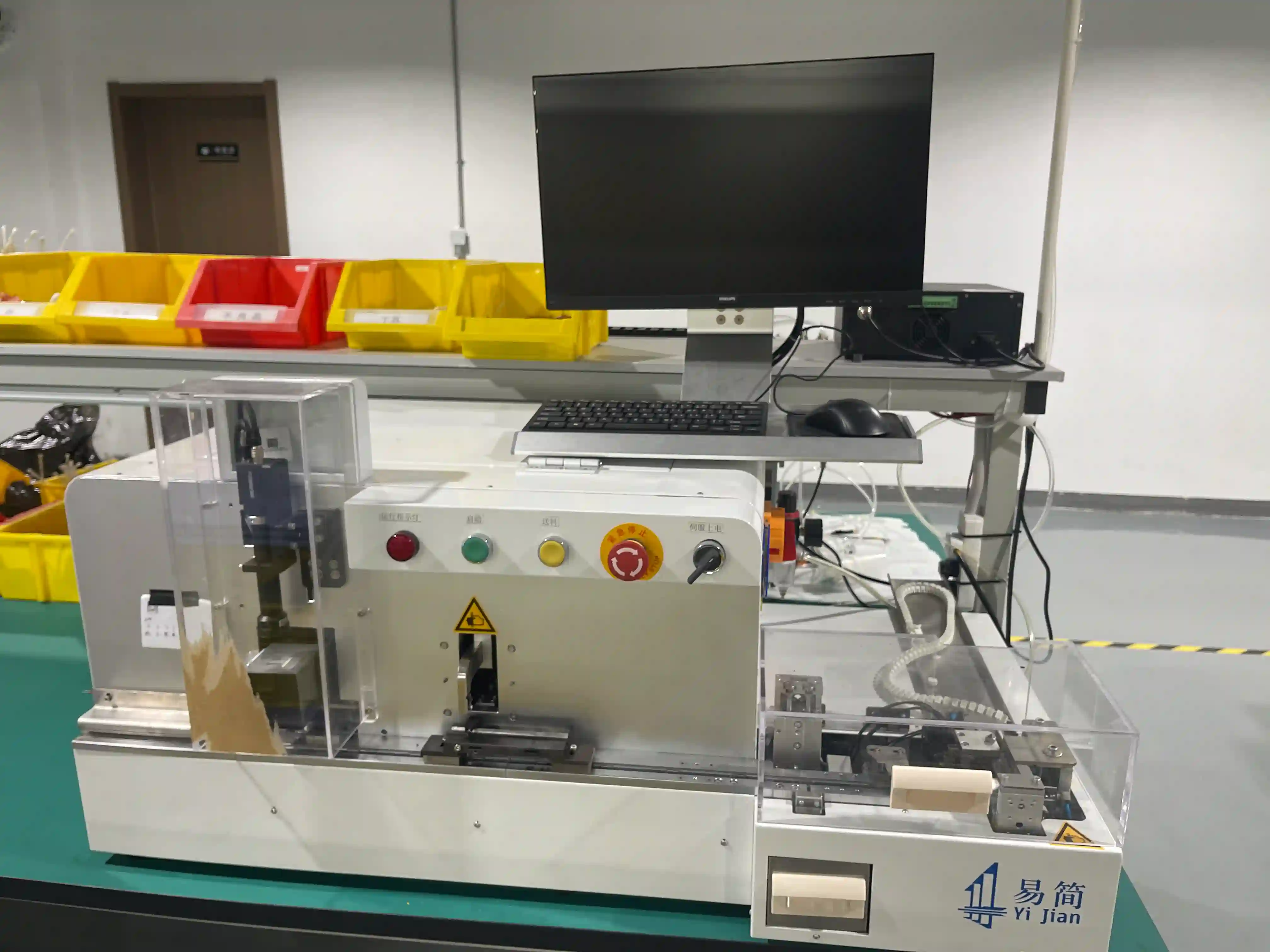
Custom Overmolding Process
Our overmolding process combines precision injection molding with expert cable assembly for reliable, professional results.
Design Review
Review your requirements and recommend mold design
Tooling
Create custom mold tooling for your connector
Cable Assembly
Terminate cables with connectors
Overmolding
Injection mold over connection points
Testing
Verify electrical and mechanical performance
Complete Overmold Solutions
From prototype to production, we provide complete overmolded cable solutions including tooling design, material selection, and quality testing.
- Custom mold tooling design
- Multiple material options
- IP67/IP68 sealing capability
- Custom color matching
- Logo embossing/debossing
- Strain relief integration
- In-house injection molding
- 100% electrical testing
Prototype Options
Need overmolded cables but not ready for production tooling? We offer alternatives for prototyping and low volumes.
- Pre-made molded boots
- Heat shrink strain relief
- Backshell alternatives
- Soft-tool prototype molds
- Bridge to production
Custom Overmolded Cable Assembly Manufacturing
As a specialized overmolded cable assembly manufacturer — also called molded or injection-molded cable assemblies — OurPCB delivers overmolded cables and connectors with integrated strain relief and environmental protection. Our cable assembly expertise includes custom mold tooling, material selection, and precision overmolding for professional OEM products.
Overmolding provides key advantages: integrated strain relief protecting the cable-to-connector junction, IP67/IP68 environmental sealing for waterproof applications, enhanced durability against pulling and flexing, and professional appearance with custom branding opportunities.
Material options include PVC for economical general-purpose applications, TPE for soft-touch feel and flexibility, TPU for abrasion and oil resistance, and silicone for high-temperature and medical device applications requiring biocompatibility.
Industries served include automotive with sealed under-hood connections, medical devices requiring cleanable sealed cables, consumer electronics seeking professional appearance, and industrial equipment needing rugged protection.
For prototyping and low volumes before production tooling investment, we offer alternatives including molded boots, heat shrink strain relief, and soft-tool prototype molds. Rapid prototyping validates your design before production commitment. Contact us for overmolded cable assembly quotes.
Overmolded Cable FAQ
Overmolded cables provide several advantages: integrated strain relief protecting the cable-to-connector junction, environmental sealing (waterproof/dustproof), improved durability against pulling and flexing, a professional finished appearance, and custom branding opportunities. They're ideal for products requiring reliability in harsh conditions.
We offer various overmold materials including PVC (economical, general purpose), TPE (soft touch, flexible), TPU (high abrasion resistance), silicone (high temperature, biocompatible), nylon (high strength), and specialty materials. Material selection depends on your application requirements including flexibility, temperature, and chemical exposure.
For overmolded cables, there is typically a minimum quantity due to the tooling and setup involved. However, we offer flexible solutions - for prototypes or small batches, we can provide alternatives like molded boots or heat shrink solutions. For production quantities, custom overmolding becomes cost-effective.
Yes, we can produce overmolds in custom colors to match your product design. Standard colors are readily available, and custom color matching is possible for production quantities. We can also add logo embossing or debossing to the overmold for branding.
Single-shot overmolding places one molding compound around the prepared cable and connector insert in one molding operation. Two-shot or multi-shot molding uses separate molding stages, often to combine a rigid support or seal geometry with a softer outer strain relief, or to create distinct colors or functions. The right process depends on material compatibility, part geometry, performance requirements, volume, and whether the added tooling and process complexity provide a useful benefit.
The main drivers are part size and geometry, cavity count, required tool life, connector and cable shutoff complexity, inserts or slides, gate and vent strategy, surface finish, dimensional requirements, and the number of molding materials or stages. Soft tooling can be appropriate for design learning or lower-volume builds, while hardened production tooling is chosen for repeatability and wear life. A DFM review identifies these drivers before tooling is released.
Get an Overmolded Cable Assembly Quote
Send your drawing, connector list or BOM — an engineer replies with a DFM-checked quote and lead time. Overmolded strain relief, IP67 sealing, custom tooling.
- Free quote in 24 hours
- MOQ from 1 pc — prototype to volume
- Built to IPC/WHMA-A-620 & ISO 9001
- NDA on request — files kept confidential
Request a Quote
Response within 24 hours
Real Project Example
Overmolded power cable — from silicone-mold samples to a scaling NPI program
A North American energy / electrification company needed to validate a complex custom overmolded power cable before committing to hard production tooling. To avoid the cost and lead time of a hard tool for an early NPI build, we proposed silicone (soft) tooling—allocating 50 pieces of raw material to produce 5 sample units, delivered in a 3–4 week turnaround (including roughly two weeks to build the silicone mold) so the customer could run physical testing and iterate without an upfront hard-tooling investment.
As the program matured over a 1+ year NPI cycle—with continuous drawing, diameter and flexibility updates and overmolded, shrouded cable ends—projected volumes scaled from an initial 2K / 5K / 10K to 20K / 60K / 100K. We sustained the engineering and commercial alignment across the customer's NPI, mechanical-engineering and supply-chain teams as the MOQs grew.
De-identified from real project records; customer identity withheld under NDA. See more project scenarios.
Need Overmolded Cable Assemblies?
From custom tooling to production molding, we manufacture overmolded cables with integrated strain relief and environmental protection.