Overmolding & Insert Molding
Custom overmolding and insert molding for cable assemblies providing strain relief, environmental sealing, and connector protection.
Molding Methods for Cable & Connector Work
The right method depends on insert sensitivity, sealing needs, finished geometry, production volume, and tooling economics.
Overmolding
Use for integrated strain relief, grip, geometry, and sealing around a cable or terminated connector.
Low-Pressure Hot-Melt Molding
Use around delicate electronics when conventional injection pressure could disturb components or solder joints.
Insert Molding
Use to capture contacts, bushings, terminals, or other hardware directly within a molded body.
Two-Shot / Multi-Shot
Use when one part needs distinct materials, durometers, colors, grip zones, or sealing features at production volume.
Potting & Encapsulation
Use when cavity filling and electronics protection matter more than a molded exterior with precise finished geometry.
Process Selection
Choose by insert sensitivity, seal path, mechanical load, cosmetic needs, expected volume, and tooling economics.
Protection & Performance
Molding can combine strain relief, sealing, connector protection, grip, and identification in one designed interface. The process must be matched to the cable jacket, insert, load path, environment, and inspection plan—not selected by exterior shape alone. For product-focused examples and construction options, see our overmolded cable assemblies page.
- Custom mold design and build
- TPE and PVC overmolding
- Silicone molding capability
- Multi-shot molding options
- IP67/IP68 sealed assemblies
- Strain relief boots
- Connector backshells
- Logo and branding options
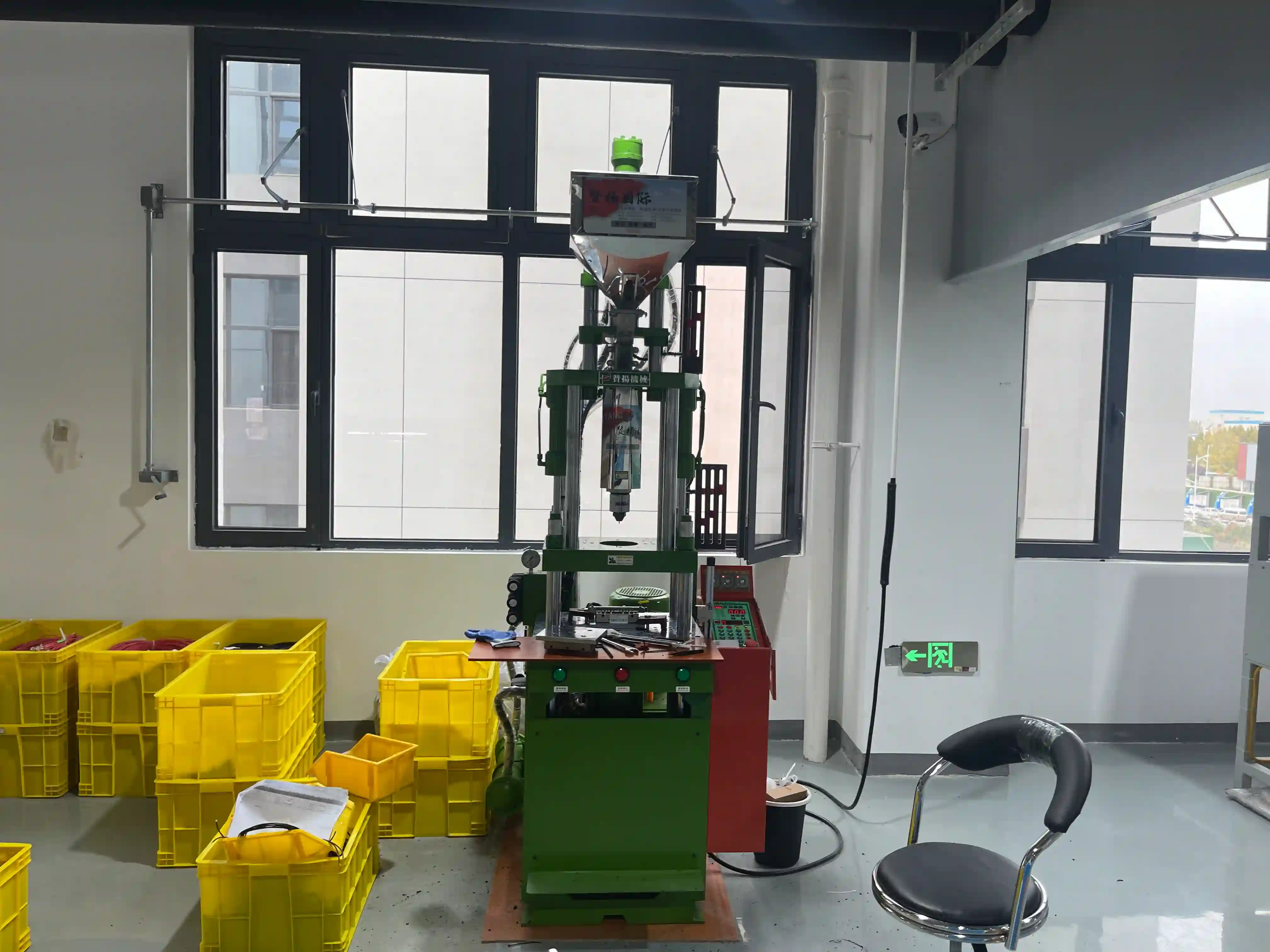
Process and DFM Considerations
Cable molding DFM balances polymer flow and tool closure against the limits of wires, contacts, circuit boards, jackets, and seals.
Pressure, Heat & Insert Stability
Clamp force, injection pressure, melt temperature, and exposure time must suit the insert. Delicate solder joints, fine conductors, sensors, and board components may favor low-pressure hot-melt encapsulation or potting over conventional injection molding.
Wall, Flow & Gate Strategy
Uniform walls help fill and cool consistently. Gate position should fill around the insert without shifting it, trapping air, creating weak knit lines at a seal path, or concentrating stress where the cable flexes.
Adhesion & Mechanical Retention
A chemical bond requires compatible, clean material surfaces and a controlled process. When dependable chemical adhesion is unlikely, grooves, ribs, holes, undercuts, and other mechanical keys create a physical load and leak path barrier.
Shutoffs, Masking & Flash Control
Tool shutoffs must close around variable cable and insert geometry without damage. Masking protects contacts, mating faces, vents, and functional surfaces; locating features reduce movement and help control flash.
Tooling Type
Soft or bridge tools can reduce initial commitment and support design learning. Hard tools become appropriate when cycle consistency, cavity count, surface requirements, and expected tool life outweigh the higher upfront investment.
Cost & Schedule Drivers
Part envelope, cavities, side actions, insert loading, shutoff complexity, runner and gate design, finish, tolerances, tool material, sampling, and validation iterations drive tooling cost and timing. Part price also reflects material, cycle, scrap risk, and loading labor.
Material Families and Selection
Grade-level data and compatibility testing should confirm the final choice; family names alone do not determine performance.
How Molded Assemblies Are Verified
The verification plan should trace each check to fit, retention, flex life, sealing, or internal molding quality.
Dimensional & Visual
Checks critical interfaces, connector fit, flash, short shots, exposed conductors, cosmetic surfaces, and the molded profile.
Pull & Flex
Evaluates whether the strain-relief geometry, cable retention, and molded interface carry expected mechanical loading without damage.
Seal-Oriented Testing
Uses the product's specified ingress, leak, or pressure-decay method to evaluate the complete seal path rather than assuming a molding process creates a rating.
First-Article Sectioning
Destructive cross-sections can reveal voids, incomplete fill, jacket interaction, conductor position, bond-line condition, and material coverage hidden from external inspection.
Acceptance criteria come from the drawing and application requirements. See our cable assembly testing capabilities for related electrical and mechanical verification methods.
Engineered Protection
From simple strain relief boots to complex sealed connectors, our molding capabilities add the protection and functionality your cable assemblies need for demanding applications.
Strain Relief
Cable flex protection
Sealing
Designed and tested as a complete interface
Branding
Logo and color options
Custom
Tailored solutions
Selecting a Cable Molding Process
Overmolding creates a defined exterior around a cable, connector, or subassembly and is often chosen for strain relief, grip, protection, identification, and a designed seal path. It is a good fit when finished geometry and repeatable production are central requirements. For construction details and product examples, visit the overmolded cable assembly page.
Low-pressure hot-melt molding is different: polyamide-based material flows around electronics with lower mechanical loading than conventional injection molding. It is useful for delicate circuit boards, sensors, solder joints, and small conductors, provided the material's temperature, adhesion, and environmental behavior suit the application. Insert molding instead locates terminals, contacts, bushings, or hardware in a tool and forms the body around them, reducing downstream assembly while making insert location and shutoff design critical.
Two-shot or multi-shot molding combines distinct materials or colors in one molded construction. It can separate a rigid support from a flexible strain-relief zone or add grip and identification features, but additional tooling and process complexity need enough functional or production benefit to justify them. Potting and encapsulation fill a cavity around electronics with a curable material; they are preferable when internal coverage and environmental isolation matter more than a precise molded exterior. Our potting capability covers that related process.
Thermoplastic families support defined, remeltable molded shapes and range from flexible elastomers to rigid engineering resins. Hot-melt polyamides emphasize low-pressure encapsulation and adhesion. Thermoset epoxies, polyurethanes, and silicones cure in place for potting and cannot be selected interchangeably: operating temperature, flexibility, chemical exposure, moisture path, jacket compatibility, serviceability, and desired bond all influence the choice. Material screening should consider both a chemical bond and mechanical keying because adhesion to cable jackets can vary by compound and surface condition.
Sealing is a system outcome across the cable jacket, molded material, connector, and every interface. A waterproof cable assembly therefore needs a defined ingress requirement and a matching finished-assembly test. Similar DFM discipline matters in vibration, fluid-exposure, or repeated-flex applications such as automotive cable and harness applications. Contact us with drawings, insert details, materials, environmental requirements, expected volume, and validation needs so the molding process can be evaluated.
Molding FAQ
Overmolding provides strain relief at cable-to-connector junctions, seals cable entries against moisture and dust, adds grip surfaces, and creates custom shapes around connectors. It improves durability and environmental protection.
We mold TPE (thermoplastic elastomer), PVC, silicone, polyurethane, and nylon. Material selection depends on flexibility requirements, temperature range, chemical resistance, and environmental sealing needs.
An IP-oriented result depends on the complete assembly and test method, not molding alone. Seal paths, cable jacket compatibility, connector interfaces, void control, and process consistency must be designed together, then verified on the finished assembly against the required ingress test.
Conventional overmolding is well suited to defined exterior geometry, strain relief, grip features, and robust production cycles. Low-pressure hot-melt molding uses lower clamp and injection loads around sensitive electronics, making it useful when components, solder joints, or small wires could be displaced or damaged. Material needs and finished-part geometry also affect the choice.
The main drivers are part size and geometry, undercuts and side actions, cavity count, shutoff complexity around cables and inserts, surface finish, tolerance strategy, runner and gate design, tool material, and the number of validation iterations. Soft or bridge tooling can support learning and lower-volume needs; hardened production tooling costs more but is selected for durability and repeatability.
Real Project Experience
How we've handled similar wire harness and cable assembly projects
See de-identified project scenarios — supplier qualification, connector-shortage recovery, lead-time compression, and engineering spec lockdown — drawn from real production records.
Need Overmolding Services?
Custom overmolding and insert molding for strain relief, environmental sealing, and connector protection in your cable assemblies.