
As OEMs scale production of electronic sub-systems, achieving cost-efficient, high-reliability interconnects becomes critical. IDC (Insulation Displacement Connector) cable assemblies leverage mass-termination ribbon cable to connect multiple signals in a single operation, eliminating wire stripping and reducing manual labor. These assemblies are ideal for board-to-board data and signal transfer in applications from automotive ECUs to industrial controllers.
What Is an IDC Cable Assembly?
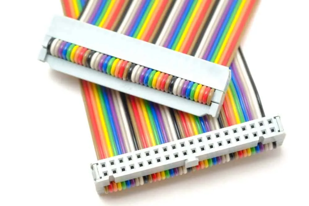
An IDC connector uses sharpened blades to pierce a wire’s insulation and form a gas-tight cold weld with the copper conductor. This solderless technique is typically paired with flat ribbon cable, enabling the simultaneous termination of many parallel conductors. Originally prevalent in computer data busses, IDC technology is now widely adopted in automotive, medical, and industrial equipment for low-frequency signal routing.
IDC vs. Crimp Termination
Both IDC and crimp are solderless termination methods, but they differ significantly in production throughput. Crimping joins one conductor at a time and requires insulation stripping; IDC terminates an entire ribbon cable in a single press without any wire preparation. This mass termination capability reduces assembly time by up to 50%, minimizes operator error, and supports the high volumes typical of OEM manufacturing.
How the IDC Connector Works
The connector body houses two offset rows of sharp U-shaped blades. The offset is half the cable pitch—for example, a 2.54 mm pitch connector has rows offset by 1.27 mm—so it mates precisely with standard ribbon cable. During assembly, the ribbon is pressed into the connector, forcing each wire between the blades. The blades slice through the insulation and form a reliable cold weld on both sides of the conductor. An integrated strain‑relief clamp secures the cable and protects the connections from mechanical stress.
IDC Connector Configuration and Pin Numbering
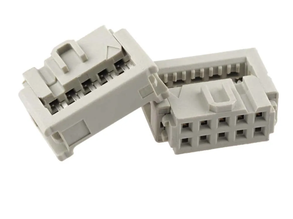
IDC connectors consistently arrange pins in two rows with odd-numbered pins on one row and even-numbered on the other. A visual indicator—typically a red mark or raised triangle—identifies pin 1, and the ribbon cable’s red‑colored wire (or another fiducial mark) aligns with this indicator. This standardized orientation ensures error‑free assembly and straightforward identification of signal paths.
Typical IDC Cable Assembly Layouts
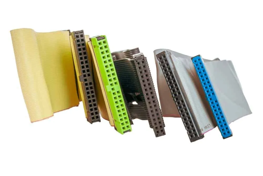
While specific legacy PC formats (40‑pin IDE, 44‑pin 2.00 mm, 50/68‑pin SCSI) still appear in some industrial applications, modern OEMs more broadly specify IDC assemblies based on pitch and conductor count:
- 2.54 mm pitch – common for low‑density control and data signals (10 to 40 positions)
- 2.00 mm pitch – used in compact storage and embedded computing modules
- 1.27 mm pitch – higher‑density interconnects for test instruments and avionics
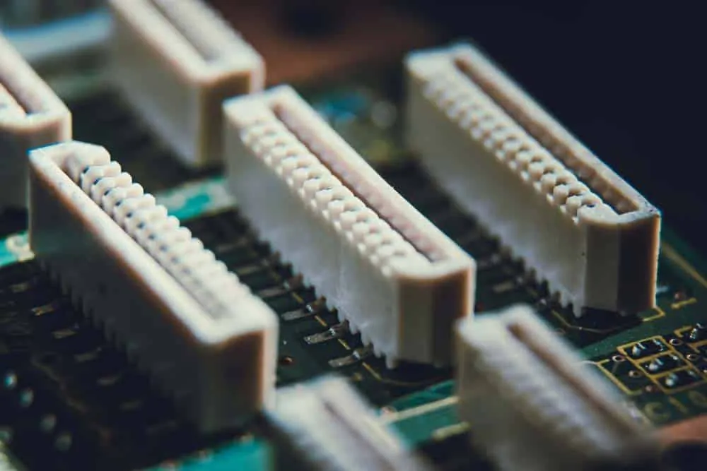
These connectors typically serve internal board‑to‑board links in industrial PCs, diagnostic equipment, HVAC controllers, and infotainment head‑units, where moderate data rates and rugged reliability are required.
Advantages of IDC Cable Assemblies
- Rapid Mass Termination – terminating dozens of conductors in one stroke slashes labor time and cost.
- No‑Strip Cold Weld – the insulation‑displacement process creates a gas‑tight, oxidation‑resistant joint that withstands shock and vibration.
- Integrated Strain Relief – built‑in clamps hold the ribbon cable, reducing the risk of fretting and fatigue.
- Consistent Quality – automated press tools deliver repeatable contact insertion depth and alignment, minimizing variations.
Disadvantages and Limitations
- All conductors in a given connector must be the same wire gauge, typically restricted to 22 AWG maximum, limiting current capacity.
- Ribbon cables can be bulkier and require more routing space compared to individual wires.
- The connector family offers fewer high‑speed differential signal options; IDC is best suited for rates up to a few Mbps.
- Not designed for repeated flexing unless specified with high‑flex ribbon.
IDC Cable Assembly Selection and Implementation Considerations
- Confirm ribbon pitch matches the connector pitch exactly to avoid misalignment.
- Verify wire gauge and conductor type (solid vs. stranded) meet the connector’s specification.
- Match the number of ribbon conductors to the connector’s available U‑channels.
- Incorporate strain relief and, if the environment demands, conformal coating or sealed connectors.
- Assess temperature range and UL flammability ratings for end‑product compliance.
Design for Manufacturing (DFM) and Certification Considerations
For OEMs supplying regulated sectors, IDC cable assemblies must conform to stringent industry standards. IPC/WHMA‑A‑620 (Requirements and Acceptance for Cable and Wire Harness Assemblies) defines workmanship criteria for crimping, soldering, and insulation‑displacement terminations. Depending on the application, certification to Class 2 (dedicated service) or Class 3 (high‑reliability) is expected. IATF 16949 governs automotive quality management systems, emphasizing defect prevention, continuous improvement, and production part approval process (PPAP). Suppliers holding IATF 16949 certification demonstrate the process controls essential for vehicle electronic assemblies.
Aerospace primes typically require AS9100 certification, which builds on ISO 9001 with additional traceability, risk management, and first‑article inspection requirements. Medical device manufacturing falls under ISO 13485, which mandates process validation, design controls, and risk management (per ISO 14971) to ensure patient safety. When selecting an IDC assembly partner, OEMs should verify the appropriate certifications are in place and review the supplier’s test capabilities—including contact resistance, dielectric withstanding voltage, and thermal cycling—against IPC/WHMA‑A‑620 acceptance criteria.
From a DFM perspective, best practices include employing automated IDC termination presses with vision systems to verify alignment and insertion depth. Connector and cable should be explicitly designed as a system, with documented process parameters for insertion force and dwell time. Post‑assembly cleaning procedures must be defined when no‑clean flux residues are incompatible with conformal coating or vacuum environments. Strain‑relief design should be validated through mechanical shock and vibration testing to prevent in‑service degradation.
Partner with a Certified IDC Assembly Manufacturer
IDC cable assemblies offer proven, cost‑effective signal interconnect solutions for high‑volume OEM production. To ensure your project meets performance, regulatory, and reliability targets, partner with a manufacturer that holds the necessary certifications and offers custom design support. Contact cableharnessassembly.com to discuss your requirements—our team will provide recommendations tailored to your application and industry.
An earlier version of this article first appeared on autowiringpro.com. This version has been rewritten and updated for OEM and procurement audiences.