Engine Wiring Harness: Design, Materials, and Failure Prevention
A comprehensive guide to engine wiring harness design, material selection, routing best practices, and failure prevention strategies for automotive and heavy-duty applications.
What Is an Engine Wiring Harness?
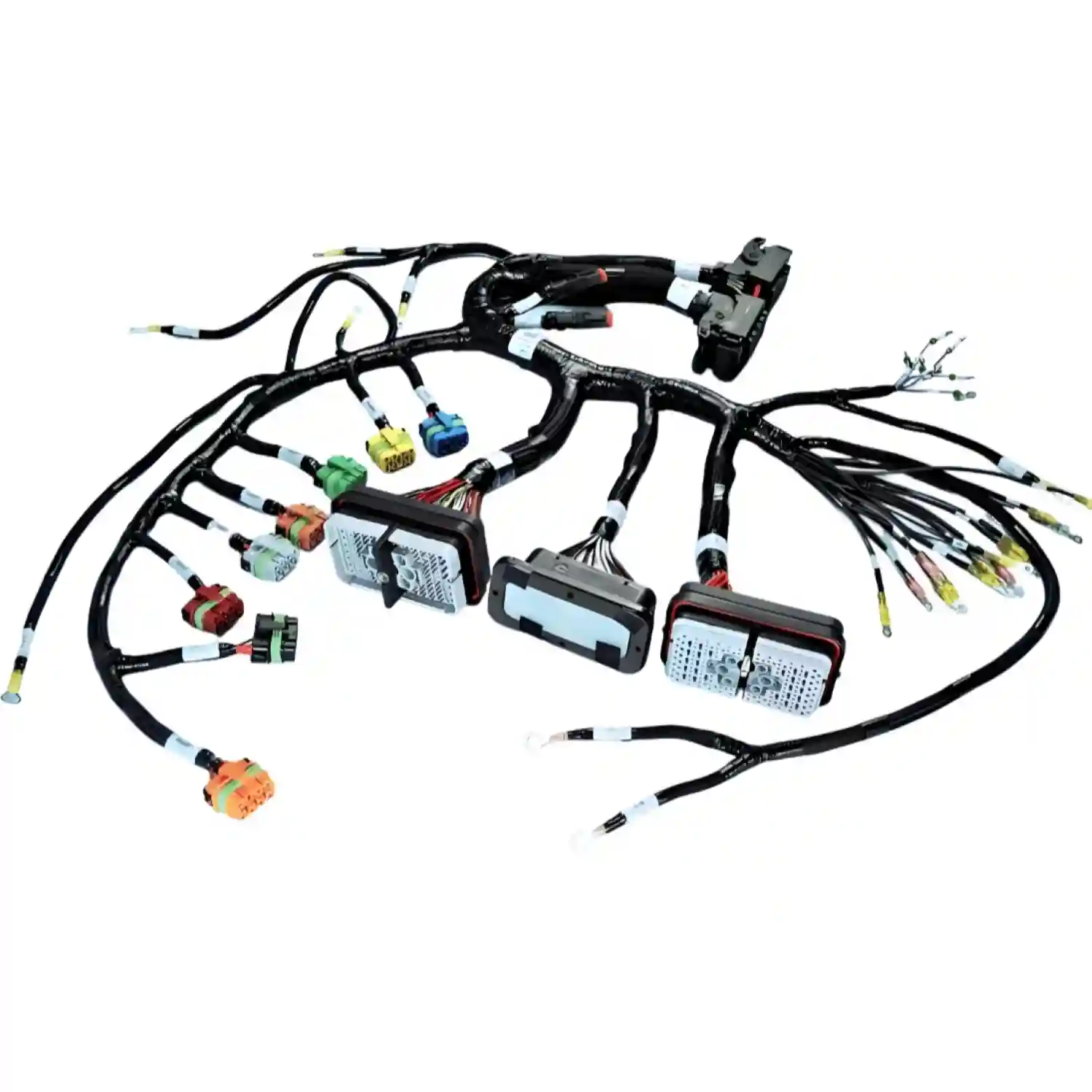
An engine wiring harness is the central nervous system of a vehicle's powertrain. It bundles dozens—sometimes hundreds—of individual wires, connectors, terminals, and protective elements into an organized assembly that links the engine control unit (ECU) to sensors, actuators, injectors, ignition coils, and emissions components. Unlike a generic wire harness, an engine harness must endure extreme under-hood conditions: sustained temperatures above 150 °C, constant vibration, oil and coolant exposure, and repeated thermal cycling from cold starts to full operating temperature.
A well-designed engine wiring harness ensures reliable signal integrity, minimizes electromagnetic interference (EMI), and provides serviceability for diagnostics and repair. A poorly designed one becomes a source of intermittent faults, costly warranty claims, and even safety-critical failures.
Key Components of an Engine Wiring Harness
Understanding the building blocks of an engine harness is the first step toward specifying or improving one.
Conductors
Copper alloy conductors—typically tin-plated or nickel-plated—form the backbone. Strand counts and gauge sizes vary by circuit current and voltage drop requirements. For example, fuel injector circuits often use 20 AWG wire, while starter motor feeds require 2 AWG or larger.
Insulation Materials
Under-hood insulation must resist heat, oil, and abrasion. Common choices include:
- Cross-linked polyethylene (XLPE): Rated to 150 °C, excellent abrasion resistance
- Ethylene tetrafluoroethylene (ETFE): Rated to 200 °C, superior chemical resistance
- Silicone rubber: Rated to 200 °C+, highly flexible but less abrasion-resistant
For a deeper comparison of insulation materials, see our guide on PVC vs TPE vs silicone cable.
Connectors and Terminals
Engine harnesses use sealed, high-reliability connectors rated to at least IP67. Common connector systems include TE Connectivity's SuperSeal and AMPSEAL series, Molex MX150, and Sumitomo sealed connectors. Each terminal is crimped to precise specifications defined by IPC-WHMA-A-620 standards.
Protection and Routing Aids
Conduit (corrugated tubing), heat-shrink tubing, woven sleeves, and foam tapes protect wires from chafing, heat, and fluid exposure. Clips, brackets, and tie-downs maintain proper routing and bend radius.
"An engine harness that ignores bend radius minimums will survive bench testing but fail within 10,000 miles on the road. The vibration environment under-hood is unforgiving." — OurPCB Engineering Team
Engine Harness Design Considerations
Designing an engine wiring harness requires balancing electrical performance, mechanical durability, thermal management, and manufacturability.
1. Electrical Performance
- Voltage drop: Calculate maximum allowable voltage drop per circuit. The automotive wire harness standard SAE J1128 recommends no more than 0.5 V drop for 12 V sensor circuits.
- Current carrying capacity: Size conductors for continuous current plus a safety margin. Derate for ambient temperature and bundling per SAE AS50881.
- EMI shielding: Route sensitive sensor signals (camshaft position, knock sensor) away from high-current circuits (injector drives, ignition coils). Use twisted pairs or shielded cables for CAN bus and other communication lines.
2. Thermal Management
Under-hood temperatures vary dramatically. Exhaust manifold proximity can push local temperatures above 200 °C, while the opposite side of the engine bay may stay below 105 °C. Design strategies include:
- Specifying higher-temperature insulation near heat sources
- Adding thermal barriers (aluminum foil tape, ceramic sleeves)
- Routing sensitive circuits away from exhaust components
- Using heat-reflective conduit in high-exposure zones
3. Vibration and Mechanical Durability
Engine vibration ranges from 30 Hz to over 500 Hz, with acceleration levels exceeding 20 G in some mounting locations. Design for vibration by:
- Securing harnesses at intervals no greater than 300 mm
- Avoiding unsupported spans longer than 200 mm
- Using flexible convoluted tubing rather than rigid conduit
- Providing strain relief at every connector interface
For more on this topic, see our wire harness vibration fatigue guide.
4. Fluid and Chemical Resistance
Engine bays expose harnesses to engine oil, transmission fluid, coolant, brake fluid, fuel, and road salts. Select insulation and conduit materials rated for the specific chemicals present. XLPE and ETFE offer broad chemical resistance; PVC degrades in contact with oil and fuel.
5. Serviceability
Design for the technician. Include service loops at connectors, use keyed and color-coded connectors to prevent mismating, and provide accessible diagnostic test points. A harness that requires three hours to replace is a harness that will frustrate dealers and inflate warranty costs.
"The best engine harness is one a technician can diagnose and service in under an hour. Every extra minute of labor adds cost across the entire vehicle fleet lifecycle." — OurPCB Engineering Team
Comparison: Engine Harness Insulation Materials
| Property | PVC | XLPE | ETFE | Silicone | TPE |
|---|---|---|---|---|---|
| Max Continuous Temp | 105 °C | 150 °C | 200 °C | 200 °C+ | 125 °C |
| Oil Resistance | Poor | Good | Excellent | Fair | Good |
| Abrasion Resistance | Fair | Good | Excellent | Poor | Good |
| Flexibility at Low Temp | Poor | Fair | Good | Excellent | Good |
| Flame Retardancy | Good | Good | Excellent | Excellent | Good |
| Relative Cost | Low | Medium | High | High | Medium |
| Typical Use in Engine Bay | Low-temp zones only | Primary circuits | Near exhaust | High-flex areas | General purpose |
Common Engine Wiring Harness Failures
Understanding failure modes helps you design them out—or at least design for early detection.
Thermal Degradation
Insulation near exhaust components becomes brittle, cracks, and eventually flakes off. Exposed conductors short to ground or adjacent circuits. This is the single most common engine harness failure.
Vibration Fatigue
Repeated flexing at connector entry points and unsupported spans causes conductor strand breakage. The circuit may test fine at rest but fail under engine vibration—making it notoriously difficult to diagnose.
Connector Corrosion and Seal Failure
Moisture ingress through failed connector seals causes terminal corrosion, increased contact resistance, and intermittent signal faults. IP67-rated connectors degrade over time if seals are not properly maintained during service.
Chafing and Abrasion
Wires rubbing against engine brackets, sharp sheet metal edges, or other harnesses wear through insulation. This is especially common where harness routing was not properly defined during vehicle integration.
Oil and Chemical Swelling
PVC and some TPE compounds swell and soften when exposed to engine oil, leading to loss of mechanical protection and eventual conductor exposure.
Best Practices for Engine Harness Specification
Define the Operating Environment Precisely
Create a detailed thermal map of the engine bay. Identify maximum temperatures at each harness segment, expected fluid exposure, and vibration profiles at each mounting point. Share this data with your harness manufacturer upfront.
Specify Sealed Connectors with Appropriate IP Ratings
For under-hood applications, minimum IP67 is standard. In splash zones or off-road vehicles, consider IP68 or IP69K connectors. Always specify connector systems with secondary locking features to prevent terminal back-out.
Use the Right Crimp for the Right Terminal
Mixing crimp tooling or using incorrect die sets causes under-crimped or over-crimped terminals. Follow IPC-WHMA-A-620 Class III criteria for crimp inspection, and validate pull-test values per the terminal manufacturer's specification.
Include Service Loops and Diagnostic Access
Add 50–100 mm of service loop at every connector. This allows technicians to probe circuits without stressing the harness and provides slack for one re-termination if a terminal is damaged during service.
Validate with Environmental Testing
No engine harness should go into production without passing a full validation test plan including:
- Thermal cycling (−40 °C to +150 °C, 500+ cycles)
- Vibration testing per SAE J1455 or ISO 16750-3
- Fluid resistance per SAE J1128 or ISO 6722
- Connector seal integrity per USCAR specifications
- Continuity and hipot testing
"Skipping environmental validation to save two weeks of schedule has cost OEMs millions in field failures. The test lab is always cheaper than the warranty claim." — OurPCB Engineering Team
Engine Harness Manufacturing Process
Producing a reliable engine wiring harness involves multiple controlled steps:
-
Wire cutting and stripping: Precision wire cutting and stripping machines cut conductors to length with ±1 mm tolerance and strip insulation to the exact dimension required by the terminal.
-
Terminal crimping: Automated and semi-automated crimp presses apply terminals with controlled force and height. Each crimp is monitored for pull-out force and crimp height.
-
Sub-assembly building: Wires are routed into connectors, seals are installed, and connector housings are mated. Secondary locks and CPA (connector position assurance) devices are engaged.
-
Harness assembly on board: Wires and sub-assemblies are laid out on a forming board that replicates the engine bay routing. Taping, sleeving, and conduit are applied at specified locations.
-
Testing: 100% electrical testing checks continuity, insulation resistance, and hipot withstand. Visual inspection verifies crimp quality, connector seating, and labeling.
-
Packaging and shipping: Harnesses are carefully coiled, bagged, and boxed to prevent damage in transit. See our guide on top 10 packaging and shipping practices for details.
Aftermarket vs. OEM Engine Harnesses
A common question is whether to source an OEM-spec harness or an aftermarket replacement. The answer depends on your application.
| Factor | OEM Harness | Aftermarket Harness | Custom Engineered Harness |
|---|---|---|---|
| Design Intent | Original vehicle specification | Replacement for OEM part | Optimized for specific requirements |
| Material Quality | Per OEM specification | Varies by supplier | Per customer specification |
| Connector Systems | Exact OEM match | May use equivalent alternatives | Per design requirement |
| Validation Level | Full OEM validation | Limited or no validation | Per agreed test plan |
| Lead Time | Long (OEM production schedule) | Short (stock availability) | Medium (design + prototype + production) |
| Cost | High | Low to medium | Medium to high |
| Best Use Case | Warranty replacement, fleet maintenance | Quick repair, budget constraints | Performance builds, fleet modifications, low-volume production |
For a deeper comparison, see our guide on OEM vs aftermarket wire harnesses.
Industries and Applications
While this guide focuses on automotive engines, engine wiring harnesses are critical across multiple sectors:
- Passenger vehicles: Gasoline, diesel, and hybrid powertrains require harnesses rated for 12 V to 48 V systems
- Heavy-duty trucks and off-highway: Industrial and agricultural equipment demands higher temperature ratings and enhanced chemical resistance
- Marine engines: Saltwater exposure requires corrosion-resistant terminals and waterproof connectors
- Electric vehicles: EV traction motor harnesses share many design principles with ICE engine harnesses but operate at much higher voltages
- Stationary engines: Generators, pumps, and compressors use engine harnesses in less vibration-intensive but often thermally challenging environments
- Aerospace auxiliary power units: Aerospace-grade engine harnesses require MIL-SPEC materials and extensive qualification testing
Working with an Engine Harness Manufacturer
When selecting a partner to design or manufacture your engine wiring harness, consider the following:
-
Automotive experience: Has the manufacturer produced engine harnesses before? Ask for examples and references.
-
Testing capabilities: Does the manufacturer have in-house environmental testing? Can they perform thermal cycling, vibration, and fluid resistance testing?
-
Certifications: Look for IATF 16949 (automotive quality management system) and IPC-WHMA-A-620 certification.
-
Design support: Can the manufacturer assist with harness design, routing optimization, and material selection—or do they only build to print?
-
Prototyping speed: How quickly can they produce prototype harnesses for design validation?
-
Scalability: Can they ramp from prototype quantities to production volumes without quality loss?
At Cable Harness Assembly, we support customers from initial concept through production, with full testing capabilities and certifications for automotive and industrial applications. Contact us to discuss your engine harness project.
FAQ
What temperature rating should an engine wiring harness have?
Most under-hood harnesses require insulation rated to at least 150 °C (XLPE). Near exhaust components, use 200 °C-rated materials like ETFE or silicone. Always base your specification on a thermal map of the actual engine bay, not generic assumptions.
How long does an engine wiring harness last?
A properly designed and manufactured engine harness should last the life of the vehicle—typically 150,000 to 300,000 miles for passenger cars. Heavy-duty applications may target 500,000+ miles. Premature failures usually trace back to thermal degradation, vibration fatigue, or connector seal failure.
Can I repair an engine wiring harness instead of replacing it?
Minor damage—such as a single chafed wire or a corroded terminal—can often be repaired using OEM-approved splice methods and heat-shrink sealing. However, extensive thermal damage, multiple broken conductors, or degraded connector seals usually warrant full harness replacement for reliability.
What is the difference between an engine harness and a chassis harness?
The engine harness connects the ECU to engine-mounted sensors and actuators within the engine bay. The chassis harness distributes power and signals throughout the vehicle body—headlights, taillights, door modules, and dashboard. They are usually separate assemblies that interconnect through bulkhead connectors.
Why do engine harness connectors fail?
The most common causes are moisture ingress from degraded seals, terminal fretting corrosion from vibration, and contact force loss from repeated mating cycles. Specifying connectors with silicone seals, gold-plated terminals, and secondary locks significantly reduces failure rates.
How do I specify a custom engine wiring harness?
Prepare a specification that includes: a complete wire list (circuit name, wire gauge, insulation type, length), connector callouts with pin assignments, routing diagram, environmental requirements (temperature range, fluid exposure, vibration profile), and applicable standards (SAE, ISO, IPC-WHMA-A-620). Submit this through our quote request page for a detailed proposal.
What standards apply to engine wiring harnesses?
Key standards include SAE J1128 (low-voltage cable), SAE AS50881 (aerospace wiring), ISO 6722 (road vehicle cable), IPC-WHMA-A-620 (requirements and acceptance for cable and wire harness assemblies), and USCAR specifications for connector performance. For automotive quality management, IATF 16949 applies to the manufacturing organization.