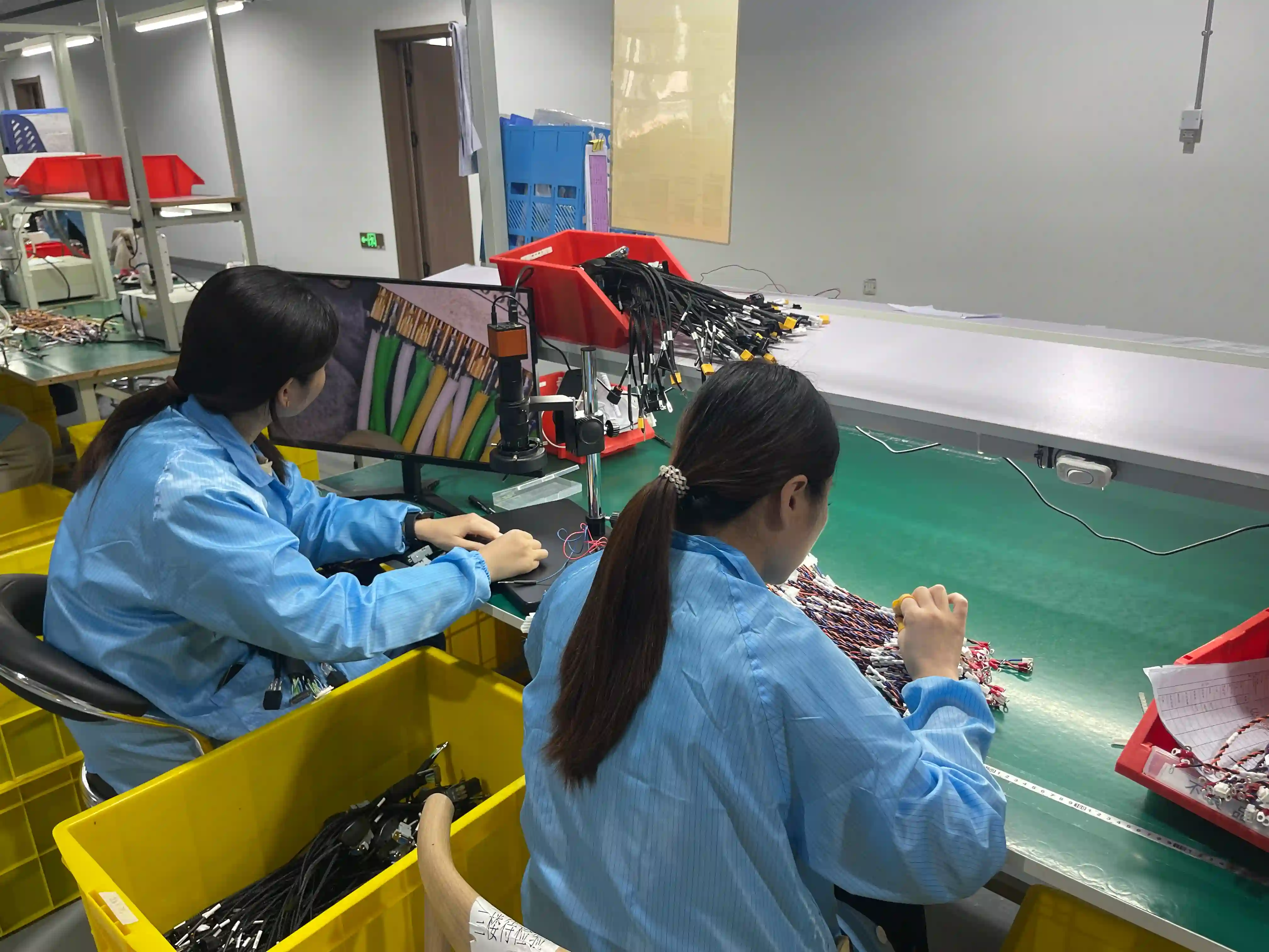
On signal-sensitive micro coax programs, it is common for a pilot build to be halted when a meaningful share of short, fine-gauge assemblies reads high impedance even though they pass continuity. The customer questions the lot, asks for recovery, and needs a test method both engineering teams can trust before any replacement units are rebuilt. The example below is an illustrative recovery flow, not a specific customer record.
TL;DR
- Continuity alone is too weak for signal-sensitive micro coax assemblies.
- Lock the fixture, test method, and first article photos before pilot production.
- Use IPC/WHMA-A-620 for workmanship and UL 758 for wire construction context.
- Sort failures by mode, then rebuild the process before replacement production starts.
Table of Contents
What Micro Coax Testing Must Prove
A micro coaxial cable is a miniature shielded cable with a center conductor, dielectric, shield, and jacket arranged around the same axis. That geometry gives the cable a controlled signal path, but it also makes the assembly sensitive to strip length, connector seating, shield handling, and bend radius.
Characteristic impedance is the effective impedance a signal sees as it travels through a cable. The concept is explained in public engineering references such as characteristic impedance, but the practical factory point is simple: a cable can pass a DC open-short test and still fail an imaging signal if the termination geometry changes.
A release plan is a controlled set of tests, fixtures, acceptance limits, records, and escalation rules used before shipment. For cable assembly work, workmanship criteria often reference IPC documents such as IPC/WHMA-A-620, while wire construction and appliance-wire context may point to UL 758 or the customer's drawing.
“On AWG#40 micro coax, the defect window is smaller than the operator's fingertip. The first article package should include the strip photo, fixture ID, and tester file before additional samples are released.”
Illustrative Recovery Flow: High Impedance
Representative scenario (illustrative) — not a specific customer record.
In this kind of program, the first mistake would be treating the complaint as a simple continuity failure. Short, fine-gauge assemblies are easy to deform during termination, and a small difference in where the fixture touches the connector can change the measured result.
The right response is to stop production, separate failed units from untested inventory, and review the customer's measurement setup against the factory fixture. Often the root cause is not one operator error: the specification definition and the test method are not aligned, so both teams read the same cable differently.
The correction is to update the specification, provide fresh test reports, build new validation samples, and release the replacement lot only after both engineering teams agree on the contact points and pass-fail logic. That approach protects the customer's schedule and gives the factory a repeatable method for the next build.
Test Method Comparison Table
| Test | What It Proves | Production Use | Release Risk |
|---|---|---|---|
| Continuity and shorts | Proves each conductor path and catches crossed or bridged circuits | 100% final test | Can miss impedance and shield geometry defects |
| Conductor resistance | Flags poor termination, broken strands, or wrong wire length | 100% or sampled by circuit criticality | Limit must match wire gauge and length, not a generic value |
| Shield continuity | Confirms braid, foil, shell, or drain path is bonded as specified | 100% when shielding is part of the function | A pigtail can pass DC but fail high-frequency performance |
| Impedance or TDR review | Finds geometry changes near strip, crimp, solder, or connector zones | First article and sampled critical lots | Requires a stable fixture and agreed measurement method |
| Magnified visual inspection | Catches nicked AWG#40 conductors, lifted shields, and dielectric damage | Setup, first article, and sampled production | Inspector criteria must be photo-based for repeatability |
| Device-level functional check | Confirms the assembly works in the real imaging, sensor, or robotics system | NPI and quality recovery lots | Slow, so it should not replace controlled production tests |
“IPC/WHMA-A-620 helps us control workmanship, but impedance-sensitive micro coax also needs a measurement agreement. If the customer and factory use different fixtures, the same 100 mm cable can produce two different answers.”
Release Plan for NPI and Production
1. Define the Drawing
Call out cable family, connector part numbers, finished length, shield termination, and test limits before sampling.
2. Freeze the Fixture
Record fixture ID, probe contact points, mating orientation, and maintenance interval before the first pilot batch.
3. Separate Test Layers
Keep continuity, shield, impedance, and functional checks as separate records so failures can be traced quickly.
Engineers buying micro coax assemblies are usually in the NPI or supplier-transfer stage. At that point, the objective is not only to get a quote. The objective is to know whether the supplier can convert a sensitive cable path into repeatable production records.
Standards help anchor the release plan. IPC/WHMA-A-620 gives workmanship language for cable and harness assemblies. UL 758 helps define the recognized appliance wiring material context where applicable. IEC 60512-style connector tests can support contact resistance, mechanical endurance, and retention planning when the customer specification requires them.
Common Failure Modes to Control
Over-stripping that exposes or weakens the center conductor near the connector.
Crushed dielectric from tooling pressure, clamp force, or a sharp bend after assembly.
Shield braid loss or uneven shield fold-back that changes the transition geometry.
Fixture contact variation between factory test, customer incoming inspection, and device validation.
Uncontrolled rework that reheats or mechanically stresses a miniature termination.
Packaging compression that creates a bend sharper than the approved routing limit.
“When a large share of a lot fails on signal, the fastest recovery is not arguing over blame. Freeze production, sort by failure mode, rebuild the test method, and only then restart the replacement lot.”
Supplier Checklist Before You Release the Order
- Drawing states cable family, wire gauge, impedance target, connector series, and finished length tolerance.
- Test method defines where probes contact the assembly and whether the fixture checks the mating face or cable side.
- First article report includes photos of strip length, shield handling, connector seating, and final bend condition.
- Tester program name, fixture ID, and revision are locked before pilot production starts.
- Any customer functional test is translated into measurable factory limits before volume build.
- Rejected units are separated by defect mode, not grouped under one broad electrical-failure code.
A capable supplier will ask for the test requirement before quoting volume. If the RFQ only includes connector photos and a length, expect delays. Send a released drawing, mating connector details, allowed substitute list, electrical limits, packaging rules, and the field failure you most need to avoid.
Internal pages that help define the surrounding purchase package include our micro coaxial cable assembly service, connector pinout verification guide, and cable shield termination guide. For broader electrical release planning, review our cable testing capabilities.
Micro Coaxial Cable Testing FAQ
How do you test a micro coaxial cable assembly before shipment?
Use 100% continuity and shorts testing, then add shield continuity, conductor resistance, visual inspection under magnification, and impedance-aware checks where the signal path is sensitive. For fine pitch assemblies such as AWG#40 100 mm leads, fixture repeatability matters as much as the tester model.
Can a micro coax cable pass continuity but fail in the device?
Yes. Continuity only proves that a conductive path exists. A damaged dielectric, uneven shield termination, excessive bend, or poor connector launch can shift impedance enough to fail imaging or sensor performance even when DC resistance looks acceptable.
What standards apply to micro coaxial cable assembly inspection?
Most programs combine workmanship criteria from IPC/WHMA-A-620 with material and insulation requirements from UL 758 or the customer's released specification. Connector mechanical checks may reference IEC 60512-style test methods when the drawing calls them out.
What sample size should be used for impedance or signal checks?
Run 100% open-short testing on production lots, then use risk-based sampling for impedance, insertion loss, return loss, or device-level signal checks. For a new micro coax design, we normally validate at least 5 to 10 first article samples before releasing the work instruction.
What causes high impedance defects in micro coax assemblies?
Common causes include over-stripped conductors, crushed dielectric, braid loss at the termination, wrong test fixture contact pressure, connector misalignment, and a drawing that does not define the measurement method. The defect can multiply quickly on small cables because the geometry tolerance is so tight.
What records should a supplier provide for micro coax cable testing?
Ask for the approved drawing revision, tester program name, first article report, continuity and shorts limits, fixture ID, visual inspection criteria, nonconformance history, and any impedance or functional test reports required by the release plan.
Need a Micro Coax Assembly Reviewed Before Sampling?
Send your drawing, connector family, target impedance or signal requirement, finished length, and test records you expect from the supplier. Our engineering team can review the release plan before prototype or production.
Request Engineering Review