TC-ER Power Cable Assembly
Industrial power cable assemblies built from specified TC-ER marked tray cable, with controlled terminations, durable strain relief, labeling, and documented electrical verification.
Built For Industrial Equipment, Not Generic Power Cord Supply
A TC-ER power cable quote usually starts with more risk than a simple cut-to-length cable. Buyers need to know whether the selected tray cable can be terminated cleanly, whether the jacket fits the gland, whether the bend radius works at the machine, and whether the finished assembly will arrive with enough labeling and test evidence for installation.
In a recent panel-to-conveyor build review, our engineering team found that the specified cable gland left less than 2 mm jacket compression margin after tolerance stack-up. We changed the gland family before pilot production, preventing field rework on 180 cable sets while keeping the original TC-ER cable selection and terminal map intact.
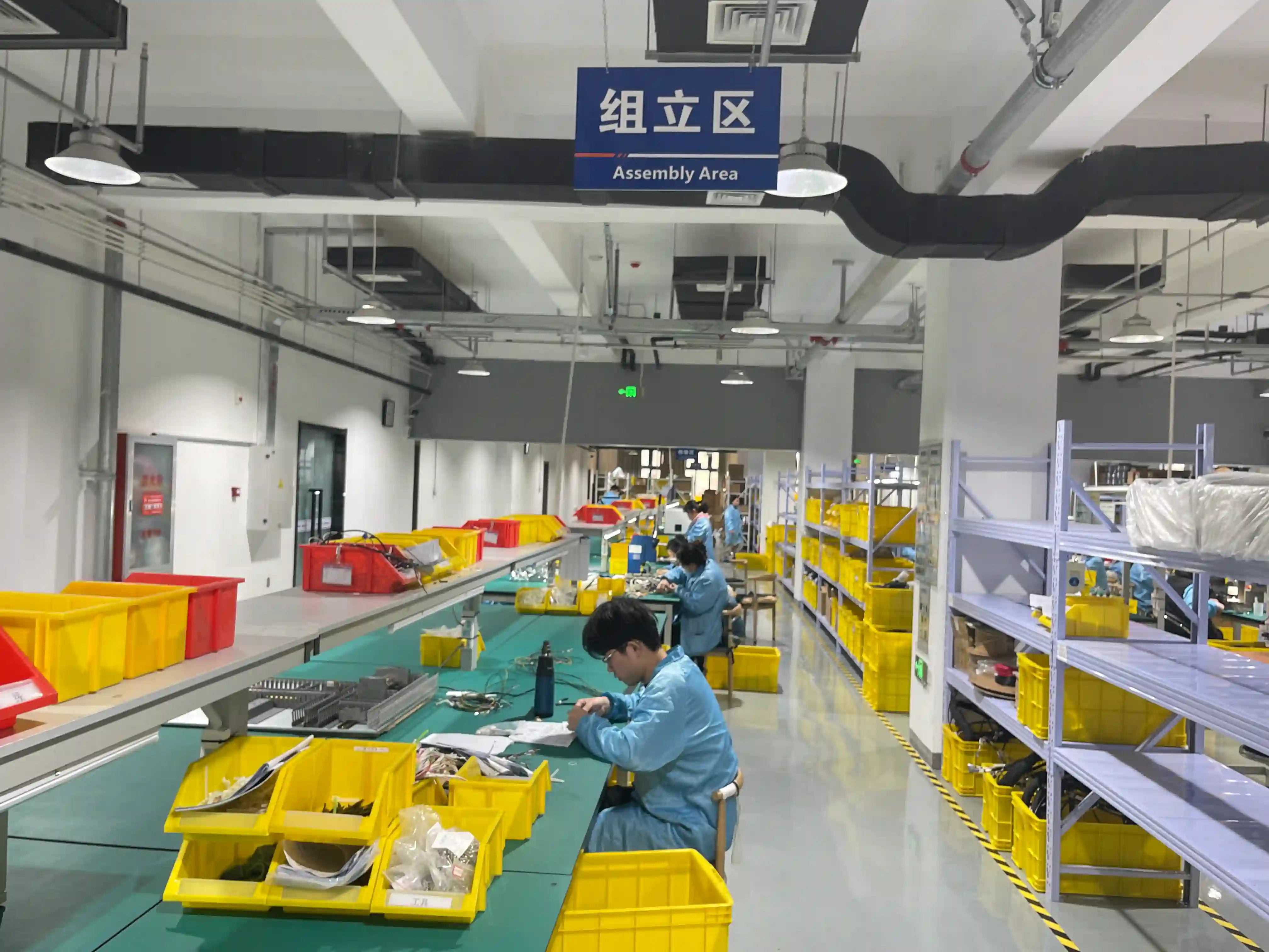
TC-ER Assembly Capability
The tray cable itself must be selected correctly, but assembly quality depends on controlled cutting, termination, marking, and release testing.
Standards And Documentation
We separate listed cable requirements, installation-code context, and assembly workmanship records so supplier qualification stays clear.
UL 1277 tray cable
Specified cable family for TC-ER marked industrial runs
We preserve the cable marking and lot traceability through cutting, termination, and packout.
NEC Article 336
Tray cable installation context
Used during RFQ review to flag routing, support, and exposed-run assumptions that belong with the installer or authority having jurisdiction.
IPC/WHMA-A-620
Cable and wire harness workmanship
Applied to strip length, conductor damage limits, crimp quality, solder sleeve use, lacing, and label placement.
ISO 9001
Quality system control
Supports controlled drawings, incoming material checks, traveler records, inspection status, and corrective action handling.
Build Process
The process is designed for repeatable industrial cable sets where the buyer needs evidence, not just a shipped cable.
Review the drawing, tray cable marking, conductor schedule, terminal map, bend radius, and installed exposed-run assumptions before quoting.
Confirm cable availability and incoming marking so the finished assembly can be tied back to the specified TC-ER cable family and lot.
Cut and strip with controlled dimensions, jacket scoring limits, conductor inspection, and operator signoff on first-piece samples.
Terminate lugs, ferrules, shields, grounds, and panel-entry components using approved tooling and pull sample checks where required.
Apply labels, heat shrink, gland kits, boots, and packout protection so installers can route the assembly without guessing conductor identity.
Run electrical verification and release the assembly with drawing revision, test data, and traceability records matched to the purchase order.
Factory KPIs Buyers Usually Ask For
Electrical test coverage before shipment
Typical drawing and manufacturability review window for complete RFQs
Quality record retention available for automotive-style programs
Existing wire-processing range across harness and cable assembly work
Where TC-ER Power Cable Assemblies Fit
The best-fit projects are industrial cable sets where tray-cable construction, field installation, and factory termination quality all matter.
Machine Power Drops
Pre-terminated power and control leads for industrial machinery, skids, conveyors, and modular equipment.
Panel-To-Equipment Runs
Install-ready cable sets between control panels, motors, drives, sensors, and field devices.
Motor And Drive Leads
Shielded or unshielded builds with grounding, labeling, and strain relief matched to the drive cabinet layout.
OEM Service Kits
Repeatable replacement cable kits packed with labels, revision control, and installation-friendly protection.
TC-ER Power Cable Assembly For Industrial OEMs
A TC-ER power cable assembly is different from a catalog power cord because the buyer is usually trying to bridge listed tray cable requirements, machine wiring needs, and controlled factory termination. We manufacture these assemblies for OEMs that already know the cable family or need a manufacturability review before releasing the drawing.
The main trade-off is stiffness versus durability. Larger tray cable and thicker jackets improve mechanical protection, but they can make panel entry, bend radius, and terminal dress difficult. Our review checks the full installed path before production, then ties cable cutting, crimping, heat shrink, strain relief, and testing into one traveler.
For motor-drive programs, a VFD cable assembly may be the better fit when shield termination and drive noise dominate the risk. For general machine power, TC-ER tray cable can be a practical option when the cable marking, conductor count, jacket, and exposed-run assumptions are specified correctly by the equipment design team.
Production release can include first-article photos, terminal pull samples, insulation resistance records, hipot data when required, label maps, and packout instructions. This gives incoming inspection and installers a repeatable reference instead of relying on tribal knowledge at the machine build stage.
When To Specify TC-ER
Buyers comparing three suppliers should ask how each supplier handles the boundary between listed cable construction and assembly workmanship. The supplier should be able to explain traceability, terminal tooling, installation assumptions, and test records without turning the discussion into a generic power-cord quote.
Use TC-ER assemblies when the drawing calls for tray cable that may leave the tray in an exposed run and still needs factory-controlled terminations.
Use standard power cords when the product only needs plug-and-cord equipment connection rather than tray-cable routing.
Use VFD cable assemblies when motor-drive noise, shield termination, and drive manufacturer instructions are the dominant design risks.
Use a full wire harness when the build needs branches, clips, multiple connector families, and form-board-controlled routing.
Author And Factory Context
Technical review by OurPCB Engineering Team The cable harness team supports wire harness and cable assembly programs for automotive, industrial, medical, and equipment OEMs, with ISO 9001, ISO 13485, and IPC/WHMA-A-620 workmanship controls available by program requirement.
For TC-ER projects, the most useful RFQ package includes the cable marking requirement, drawing revision, termination part numbers, gland or clamp details, installed bend space, required test values, and expected production release quantity.
TC-ER Power Cable FAQ
The TC-ER marking normally belongs to the listed tray cable construction, not to every downstream assembly step. We build from customer-specified TC-ER marked cable, maintain cable-lot traceability, and document the assembly workmanship, terminations, and electrical test results. Final installation compliance depends on the applicable code review and authority having jurisdiction.
Send the drawing, cable part number or required marking, conductor count and gauge, length tolerance, terminal or connector part numbers, shield/ground treatment, label map, test requirements, and expected annual quantity. Photos of the panel entry or machine routing help us check gland size, bend radius, and strain relief early.
Yes. Prototype builds are useful for confirming cable stiffness, gland fit, stripping dimensions, and terminal stack-up. Once released, we lock the traveler, terminal tooling, label format, inspection checkpoints, and test program for repeat production.
Yes. Shield termination can use drain wires, braid clamps, EMC glands, solder sleeves, or heat-shrink-backed ground leads depending on the cable construction and equipment grounding plan. We confirm this before production because the wrong shield method can make installation difficult or reduce noise control.
Typical release tests include continuity, conductor mapping, polarity, insulation resistance, hipot when specified, visual inspection, label verification, and first-piece pull checks on selected crimped terminals. The exact record format can match your incoming inspection requirements.
Related Cable Assembly Services
Power Cable Assembly
AC, DC, and high-current power cables
Cable AssemblyVFD Cable Assembly
Shielded motor-drive cable builds
Cable AssemblyIndustrial Cable Assembly
Machine-ready industrial cable sets
CapabilityControl Panel Wiring
Wiring-heavy cabinet and panel builds
CapabilityCrimping
Controlled terminal crimping and pull checks
CapabilityTesting
Continuity, polarity, insulation, and hipot testing
Real Project Experience
How we've handled similar wire harness and cable assembly projects
See de-identified project scenarios — supplier qualification, connector-shortage recovery, lead-time compression, and engineering spec lockdown — drawn from real production records.
Need TC-ER Power Cable Assemblies?
Send the cable marking, drawing, terminal list, label map, and expected quantity. We will review manufacturability, traceability, and test requirements before quoting.